
Background
Hydrogen peroxide has been in use as an antiseptic for nearly 100 years because it has been proven to be highly effective in killing most forms of bacteria, fungi, and viruses, including SARS-CoV-2, the virus that causes Covid-19. Hydrogen peroxide is effective on many different types of organisms because it works by oxidizing and thus destroying the organisms’ cell walls.
Introduction
The pharmaceutical industry has been using hydrogen peroxide vapor for over 2 decades because of its effectiveness in the gas phase. It is used to decontaminate the most critical manufacturing environments where drug products that are injected directly into patients’ veins are filled and sealed. Between each manufacturing batch or campaign, the production environment is gassed according to a validated cycle that achieves a 6-log kill, a measure of decontamination effectiveness commonly associated with sterility. Because it is a gas molecule on the order of Angstroms (1-10 m) in size, Vapor-Phase Hydrogen Peroxide (V-PHP, VHP, or vH₂O₂) easily penetrates everywhere in the application, including through HEPA filter media, and does not suffer from the same shadow-effects that can cause droplet distribution problems with competitive decontamination technologies (e.g., dry fog). This is an advantage over these other H₂O₂ based technologies, such as Aerosolized or Ionized Hydrogen Peroxide (AHP / iHP), for example. [The full technical explanation is beyond the scope of this paper but is included as Appendix B to this document because of the importance of the concepts discussed. In short, AHP or iHP technology requires liquid (so-called dry mist) droplet contact with surfaces of interest in order to achieve a validated 6-log kill process, which has a significant downside Again, please consult Appendix B for a detailed technical explanation.
Another significant advantage of the V-PHP method is safety. The by-products of the decontamination process are completely non-toxic as the sterilant compound breaks down only into water and oxygen. Consequently, it is a decontamination process that is friendly to most materials, effective at ambient temperatures and pressures, and leaves zero residue behind. To avoid leaving residues, decontamination technologies that rely on distributing a mist of fine droplets require the liquid sterilant to be so chemically pure as to be prohibitively expensive. In extreme cases, the equipment manufacturer often forces their customer base to sole-source the liquid H₂O₂ from them.
It’s an oversimplification of an extremely complex system with many variables (e.g., dry-bulb temperature, relative humidity, and H₂O₂ gas distribution all play a role), but it is worth noting that in the gas phase, H₂O₂ can achieve a complete 6-log kill with exposure to a concentration ≥ 150 – 200 parts-per-million (ppm) for at least 1-hour. At this gas concentration, the risk of corrosive damage to surfaces during the decontamination cycle is minimal. However, in the liquid phase, H₂O₂ concentration is expressed as a percentage, not a ppm value, where each 1% liquid concentration equates to 1,000 ppm. This means that a liquid solution containing 3% H₂O₂ is 15x more corrosive to surfaces than a vapor concentration of 150 – 200 ppm. Again, because of the number of different variables involved in this highly complex system, even though the 3% liquid can theoretically result in a higher ppm value, the overall cycle times are about the same if a 6-log kill is to be ensured. Therefore, with technologies that generate and distribute a fine mist of droplets, the end result is a significantly increased risk of corrosion damage compared with H₂O₂ vapor because liquid droplet contact with surfaces is required to be able to kill microorganisms.
Another benefit from hydrogen peroxide breaking down only into water and oxygen is that aeration times (aeration is the last component of each decontamination cycle where the H₂O₂ vapor is removed from the space being decontaminated, usually by ventilating the space with fresh air, or by using a catalyst that breaks down the H₂O₂ vapor into water and oxygen) are typically shorter compared with other bio-decontamination technologies such as formaldehyde or chlorine dioxide. Shorter aeration times mean shorter decontamination cycle times overall, which translates into more productive uptime for experiments in labs and BSCs. This combination of advantages is precisely what makes V-PHP decontamination the perfect choice for BSC decontamination, including the HEPA filters.
System Description
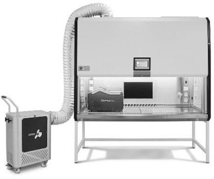
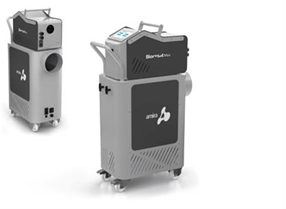
For the application, SentrySciences recommends the Bioreset® MAX from Amira Srl, a V-PHP decontamination system comprised of 3 main components:
- A close-up of a machine Description automatically generated A hydrogen peroxide vapor generation system consisting of a precision liquid pump and gas distribution blower.
- A separate catalyst and blower module that is used to break down the sterilant gas into water and oxygen.
- A combination monitoring probe from Vaisala logs data from three parameters during the decontamination cycle: Temperature, Relative Humidity (Relative Saturation), and H₂O₂ vapor concentration in ppm.
Decontamination Cycle Control
The total length of the process can vary, but it is most dependent on the size (volume) of the BSC being treated. The typical gas dwell time for a six-foot (6’) BSC is about 1-hour to achieve a 6-log kill, including HEPA filter and HEPA filter plenum decontamination. Shorter times are possible with smaller cabinets, but not significantly so if 6-log kill effectiveness is to be ensured without having to qualify the cycle for each cabinet size and type individually. A feature unique to Bioreset® MAX was designed with this safety factor in mind: the combination of Temperature / relative humidity (Relative Saturation) and H₂O₂ concentration probe is a critically important component in cycle control.
First, feedback from the H₂O₂ concentration probe is used to control the rate of injection of 35% liquid H₂O₂ in order to ensure a minimum concentration is achieved in the application for at least 1-hour. However, since V-PHP starts by vaporizing 35% liquid H₂O₂, a very important aspect of V-PHP decontamination is that care must be taken to avoid condensation of the vapor back into a liquid. At that concentration, surfaces will likely suffer some amount of bleaching or corrosion damage if condensation occurs. To prevent condensation, the Temperature / Relative-Humidity (Relative Saturation) monitoring probe provides a second and equally vitally important input for cycle control. (In the context of this paper, the terms Relative Humidity and Relative Saturation are used to describe the same measured parameter by the Vaisala probe. A more in-depth discussion can be found here: [Humidity Measurements in VHP bio-decontamination applications], but put simply, the term Relative Humidity applies when only water vapor is present in the air. The term Relative Saturation is used when both water vapor and H2O2 vapor are present in the air.)
The system senses when the Relative Saturation (RS) of the air in the BSC is approaching the dew point. When this happens, the injection of 35% liquid H2O2 is temporarily paused. When the probe detects lower Relative Saturation values, liquid H2O2 injection is restarted.
The H2O2 vapor concentration probe and the Relative Saturation probe work together to achieve optimum, and automated, cycle control. The RS probe ensures the cycle always operates just below the dew point of the air in the BSC (or room), and the H2O2 vapor concentration probe ensures the observed gas concentration in the work area stays above a minimum ppm value for at least 1 hour, which has been shown to be effective for achieving repeatable 6-log killing. In locations where the air is warm and dry, a 6-log kill can usually be achieved in just 1 hour of gassing time. However, where the air is cooler and relatively moister, the unique decontamination cycle control features of Bioreset MAX automatically ensure the cycle will run longer when required to achieve the same reproducible 6-log killing effectiveness.
A description of an example decontamination process is included as Appendix A.
Appendix A
EXAMPLE BSC DECONTAMINATION PROCEDURE
Since water and oxygen (the only by-products of the H2O2 vapor decontamination cycle) are completely non-toxic, and since the catalyst module filters 100% of the sterilant gas, setting up a BSC for decontamination using Bioreset® MAX is a short and simple exercise because the cabinet does not need to be completely wrapped and sealed, as is required when other decontamination methods are employed, such as formaldehyde or chlorine dioxide.
Note: The below example procedure is for a BSC that exhausts into the lab. If treating a BSC that’s connected to a dedicated, external exhaust, the BSC is left ON, and the catalyzer module is not used. The blower in the BSC (or the building exhaust blower, if the reason for performing the decontamination cycle is to replace a failed BSC blower) will pull the H2O2 vapor through the HEPA filters. But whether the BSC is connected to an exhaust duct, or exhausted through a HEPA filter back into the lab, because fresh air enters through the sash opening, at the end of the gassing phase, the PPM concentration in the work area will drop to zero within a few minutes. The building exhaust blower and/or the blower in the BSC (if the BSC is vented to the out-of-doors), or the blower in the catalyzer (if the BSC vents back into the lab) will continue to run for another 2-3 hours to complete the aeration process within the HEPA filter plenum.
The first step is to turn off the blower on the BSC, it is not needed during the decontamination process by design in case the reason for the decontamination exercise is to replace a failed blower. During the gassing and aeration portions of the decontamination cycle, the blower on the Bioreset® MAX catalyst module will pull fresh air in through the sash opening, causing the H2O2 vapor to flow through the cabinet, including the HEPA filters, and discharge it back into the room after it has passed through the catalyst. This ensures the BSC stays under negative pressure. With the cabinet under negative pressure and all exhaust air flowing out through a catalyst, the BSC is operating as designed to provide operator protection. So again, there is no need to 100% completely seal the BSC.
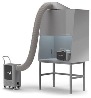
- The vapor generation module is placed on one side of the BSC work area with the H2O2 vapor outlet pointing toward the other side.
- The H2O2 liquid supply line is connected, as are the communication and power cables to the catalyst/blower module.
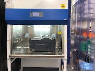
- The combination Temperature / Relative Humidity (Saturation) and H2O2 vapor concentration probe is then placed on the opposite side of the BSC from the vapor generator.
- A canopy-type duct adapter is needed to make the transition between the flexible duct and the exhaust HEPA filter housing on top of the BSC
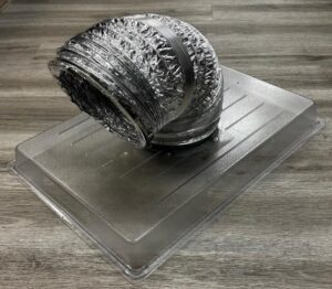
- The catalyst/blower module is then connected to the exhaust of the BSC by means of an eight-inch (8”) diameter flexible duct.
- Duct tape is used to seal the canopy adapter to the top of the BSC cabinet.
- An adjustable screw clamp is used to seal the flex duct on the inlet collar on the catalyst/blower module, and another clamp is used to seal the flex duct to the canopy adapter.
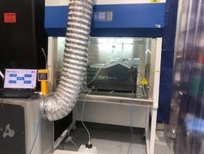
- The catalyst/blower pulls the H₂O₂ vapor ‘backward’ up through the supply HEPA filter, through the exhaust HEPA filter, and through the flexible duct all the way back to the catalyst/blower module where the catalyst breaks down the H₂O₂ vapor into water and oxygen.
- While not required, an Ethernet cable can be connected to the vaporizer module to enable remote control from a laptop.
- Finally, the BSC sash is lowered below what would be a typical working height, but it is not completely closed. This ensures negative pressure inside of the BSC without over-stressing the blower on the catalyst module.
- A 35% solution of liquid H₂O₂ is introduced to the generator via a precision pump, heated by the vaporizer, and injected into the environment to be treated by means of a small blower in the vaporizer module. (A starting temperature > 20°C and starting Relative Humidity < 70% is ideal for a successful cycle.)
- Once the gassing portion of the cycle starts, it will run for approximately 1 hour. The H₂O₂ vapor concentration inside of the cabinet will range from 500 – 800 ppm, or higher, and above the exhaust HEPA filter, H₂O₂ vapor concentration usually reaches 300 – 500 ppm
When the gassing portion of the cycle is completed, liquid injection to the vapor generator inside of the BSC is turned off and the blower in the catalyst module will continue to run to aerate the work area, the HEPA filters and the related plenum. The blower in the catalyst module will run continuously until manually powered off by the operator. In all but the largest BSCs, the aeration cycle usually is 100% complete (e.g., the H₂O₂ vapor concentration inside of the cabinet and above the HEPA filters in the exhaust plenum has reached 0 ppm) after 2-3 hours.
Important Safety Considerations
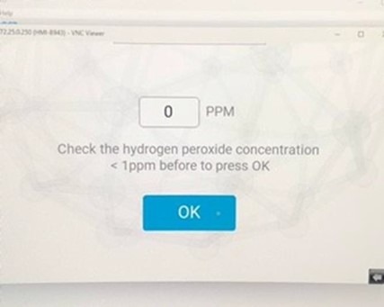
- While the combination Temp / RH / H₂O₂ concentration probe may be showing zero PPM at the end of an aeration cycle (refer to above screenshot), the actual concentration could be as high as 5-15 PPM. This is a consequence of the design purpose of the probe, which is for decontamination cycle control, not for safety level measurement. The measurement range of the probe is 0-2,000 PPM and accuracy at 10°C to 25°C is ±10 PPM or ± 5%, whichever is greater.
- Probes designed for safety level measurement can read lower PPM concentrations more accurately, but those probes would be damaged if exposed to the high concentrations of hydrogen peroxide vapor that occur during a decontamination cycle.
- If it is a safety concern for individuals or company policy requires verification of exposure limits < 1 PPM, then once the Bioreset® MAX is showing zero PPM, Personal Protective Equipment (PPE, such as a respirator approved for H2O2 gas) should be worn when entering the treatment area. Also, a hand-held gas detector (e.g., Draeger X-am 5100 or ATI PortaSens lll with a low-level H₂O₂ gas sensor) is recommended to measure actual concentration levels more accurately upon entering the treatment area. Hydrogen peroxide vapor has essentially no smell, and the first sign of exposure is usually the respiratory irritation the vapor induces.
- The U.S. Occupational Safety and Health Administration (OSHA) does not have a Short-term Exposure Limit (STEL) for H₂O₂ vapor. The OSHA Permissible Exposure Limit (PEL) is not to exceed exposure to an average concentration ≥ 1 PPM for 8 hours (e.g., Time-Weighted Average, or TWA).
- A different U.S. regulatory agency, the National Institute for Occupational Safety & Health (NIOSH) sets an Immediately Dangerous to Life and Health Limit (IDLH) of 75 PPM.
- The non-profit American Conference of Governmental Industrial Hygienists (ACGIH®) has a short-term peak exposure limit, which states that at no time should the exposure exceed 5 ppm.
- Some states like Washington and Hawaii have set their own STEL for hydrogen peroxide vapor at 3 ppm. It is a good idea to consult local country/state regulations before setting up a safety program to monitor the lab where the BSC is being treated, especially if people need to continue to work in the lab while the BSC is being decontaminated.
APPENDIX B
BSC DECONTAMINATION – SPECIAL CONSIDERATIONS FOR THE HEPA FILTERS & PLENUM
There are two main tasks that must be accomplished for a complete Biosafety Cabinet (BSC) decontamination. In addition to the obvious part that the work area must be decontaminated, the HEPA filters and plenum area inside of the HEPA filter housing must also be decontaminated. If the HEPA filters and filter housing are not effectively decontaminated prior to performing any service, such as HEPA filter or blower replacement, the safety of the technician replacing the filters or blower cannot be guaranteed. It’s also possible that microbiological contaminants or other hazards could be released into the lab where the BSC is located.
In consideration of the first half of the BSC decontamination task, the work area decontamination, there are multiple hydrogen peroxide-based decontamination technologies suitable for the task. Besides Vapor-Phase Hydrogen Peroxide (V-PHP, VHP, or vH₂O₂), which uses hydrogen peroxide purely in a gas form, Aerosolized Hydrogen Peroxide (AHP) or Ionized Hydrogen Peroxide (iHP) are technologies suitable for decontaminating the work area.
With AHP and iHP technology, instead of vaporizing liquid H₂O₂ into purely a gas form, liquid H₂O₂ is sprayed by filtered compressed air through a series of nozzles that distributes a fine mist of droplets (often referred to in the instrument literature as dry-fog) into the space being decontaminated. This is a very important distinction to understand because, and despite the marketing claims made by manufacturers of these alternative technologies, the terms ‘dry mist’ or ‘dry fog’ are inaccurate. Whether liquid H₂O₂ is aerosolized, atomized, or ionized, instead of being vaporized, the end product is the same: a very fine mist of liquid droplets on the order of 3 – 10 µm is created that must come into contact with the surface in question to kill microorganisms.
It is not possible to decontaminate the HEPA filters and HEPA filter housings with any mist of droplets, no matter how dry that mist may seem, or how many nozzles are deployed or how well-trained the operators are. Understanding why this is the case requires an understanding of how HEPA filters are designed and manufactured.
HEPA filter media is made by pressing together hundreds of thousands of polypropylene or fiberglass filter fibers arranged in a random way to create very narrow openings in the media through which air can pass. This HEPA media is then pleated to enable a very large filter surface area to be packed into a relatively small filter frame. The tightly packed fibers act like a net, trapping both small and large particles.
As the largest particles (e.g., ≥ ~1 µm) attempt to pass through the narrow pathways in HEPA filter media, the bundles of filter fibers act like a sieve, which physically blocks each particle from passing through. On the other end, extremely small particles (< 0.1 µm), are filtered out very effectively because they collide with and stick to filter fibers due to Brownian-motion style random fluctuations in their path caused by collisions with gas molecules. In between, particles are either intercepted by a filter fiber because they travel within one particle radius of a fiber and adhere to it, or the particle is small enough to avoid a filter fiber by following the contours of the air stream and the particle embeds into an adjacent filter fiber.
For the largest (≥ ~1 µm) and the smallest particles (< 0.1 µm), capture efficiency is higher than for the in-between sizes. This gives rise to the concept of Most-Penetrating Particle Size (MPPS), the particle size at which filter efficiency is rated. For HEPA filters this particle size is generally 0.3 µm with capture efficiencies ranging from 99.97% to 99.9995%, and sometimes even better, for the most critical capture applications. It may seem counter-intuitive that a HEPA filter captures both smaller and larger particles more efficiently compared with the MPPS, but it’s true. Understanding this concept is critical to understanding why AHP or iHP technology cannot be used for effective HEPA filter, and plenum decontamination in a biosafety cabinet.
In the gas phase, the size of the H2O2 molecule is approximately 3 Ångstroms (0.3 nm, or 0.0003 µm), which is 3 orders of magnitude (e.g., 1,000x) smaller than the typical MPPS for HEPA filter media. This means the H2O2 gas flows freely past the tightly arranged HEPA filter fibers and easily penetrates the plenum to achieve the same 6-log killing effectiveness more readily achieved inside the work area during the decontamination cycle.
The same cannot be said about AHP or iHP technology, even for equipment manufacturers that claim to achieve a ‘sub-micron aerosol’. Unless the mean particle size distribution of the mist droplets matches exactly the MPPS of the HEPA filter media, and more importantly unless this particle size distribution has nearly zero standard deviation of sizes (e.g., nearly zero breadth to the size distribution of droplets), almost 100% of the mist generated will impact on one side of the HEPA filter. This will result in a wet, and possibly damaged, HEPA filter with an incomplete kill downstream because none of the mist droplets were able to achieve contact with any organisms on the downside of the filter, let alone have any contact with the surfaces in the plenum area above the filter. (Don’t forget, AHP and iHP technology require direct contact between the mist droplets and the target organisms.)
Said another way, and again, when it comes to ensuring the supply and exhaust HEPA filters and the air plenum between them is effectively decontaminated to a minimum 6-log kill, it does not matter how dry the mist may seem, how many nozzles are deployed or how well-trained the operators are, only H₂O₂ in the purely gas form can provide the required result.
Acknowledgments
SentrySciences wishes to thank Dr. Dan Storey and CMDC Labs, located in Longmont, CO, for offering unlimited use of his laboratory and Biosafety Cabinet. Without him, our Biosafety Cabinet decontamination study would never have happened.
SentrySciences also wishes to express our profound gratitude to Pietro Beltramo, Product and Export Manager at Amira Srl, for providing valuable project management guidance, technical advice, and other input throughout the execution of the Biosafety Cabinet decontamination study. We are proud to be the exclusive distributor of Amira Srl products in the United States.
About the Authors
Mark Berdovich, Director of Sales, has nearly 30 years of experience solving customer problems related to particles and other unwanted sources of contamination. Starting in 1995 with Micro Measurement Labs, a particle testing laboratory and particle standards manufacturer, Mark received his GMP training and spent 6 years developing products and test methods for customers and in support of a sister company distributing particle counting and sizing instruments. In 2001, he was offered an opportunity to move to Florida to launch a new Southeast Territory for a design-build cleanroom construction contractor. After successfully building a multi-million-dollar territory from zero, he accepted an opportunity to move to Colorado in 2008 to manage the systems installation and validation services group at Particle Measuring Systems. He joined the SentrySciences team in 2017 and is proud to be leveraging his GMP and Project Management experience to serve customers’ monitoring system needs. Mark has a B.S. in Mechanical Engineering from the University of Illinois at Urbana-Champaign.
Don Pfeffer, Product Marketing – Biodecontamination Products, founded Accurate Reimbursement Solutions, Inc. a healthcare revenue cycle management company in July 1996. As president and Chief Executive Officer, he was responsible for managing the company’s overall direction, market strategy, and business development. He retired from Accurate Reimbursement Solutions in July of 2019 and joined SentrySciences to put his healthcare and clinical experience to use developing applications and strategies for SentrySciences’ family of biodecontamination products, Bioreset from Amiral Srl. Don received his bachelor’s degree from Ohio University and his MBA from the University of Phoenix.